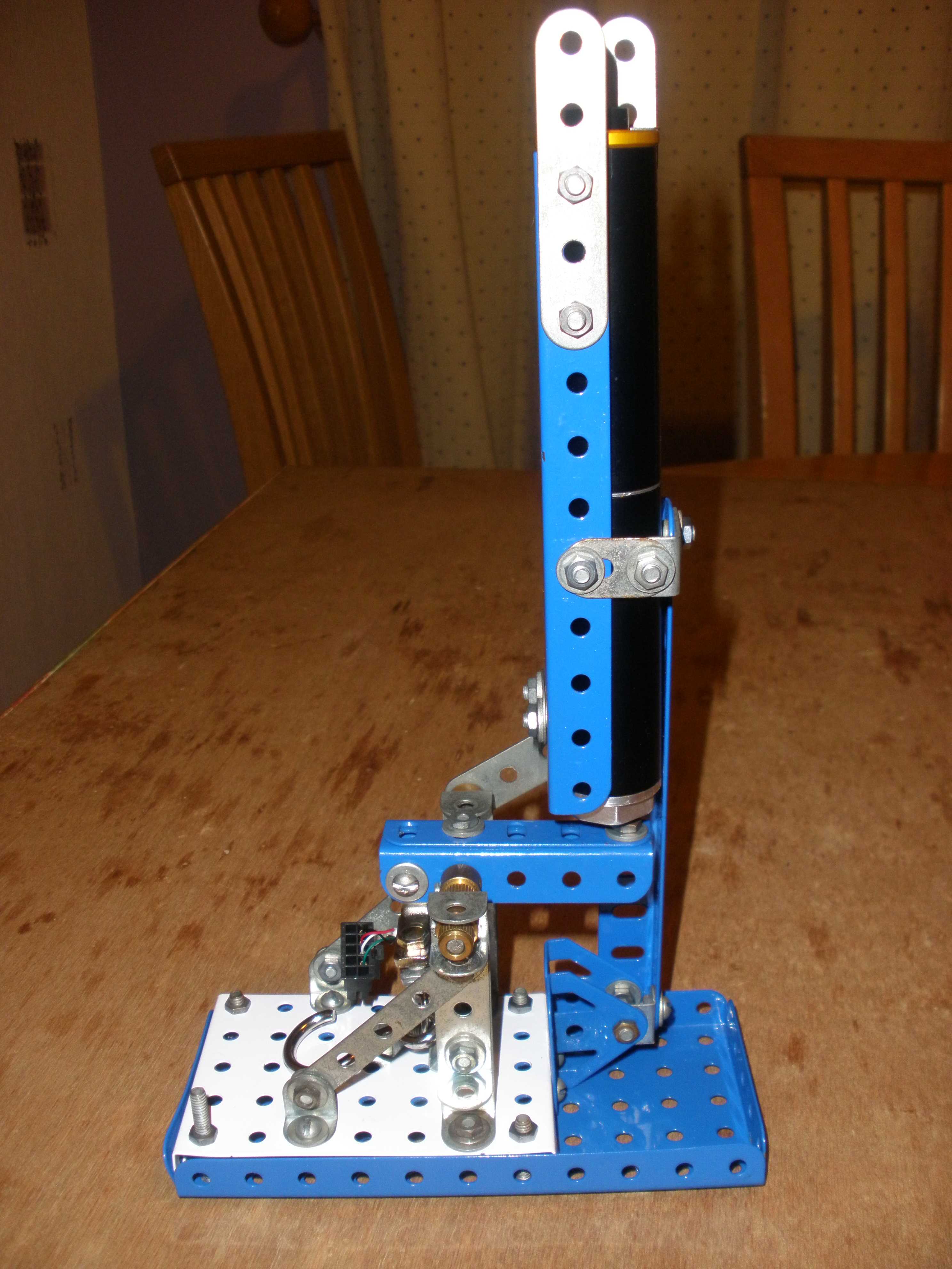
To go with the hybrid motor project, I needed a test stand. It's hard to design a model for your motor if you don't know its thrust curve. And here it is, with the motor loaded. [An alternative way of designing a model would be to try to calculate the amount of thrust from the motor].

Unfortunately for everyone else in the house it means almost all our Meccano is now semi-permanently dedicated to rocket science.
The motor is forward end down (nozzle at the top). It could work this way up for solid fuel motors, but for the hybrid, I think this would be a bad idea. In this orientation it would only be gas and not liquid nitrous oxide that was being forced through the injector, which would result in a much lower mass flow rate of oxidiser and (probably) a rather unsuccessful firing. For the hybrid, I intend to use it inverted clamped to the underside of a bench.
At the heart of the test stand is the load cell.
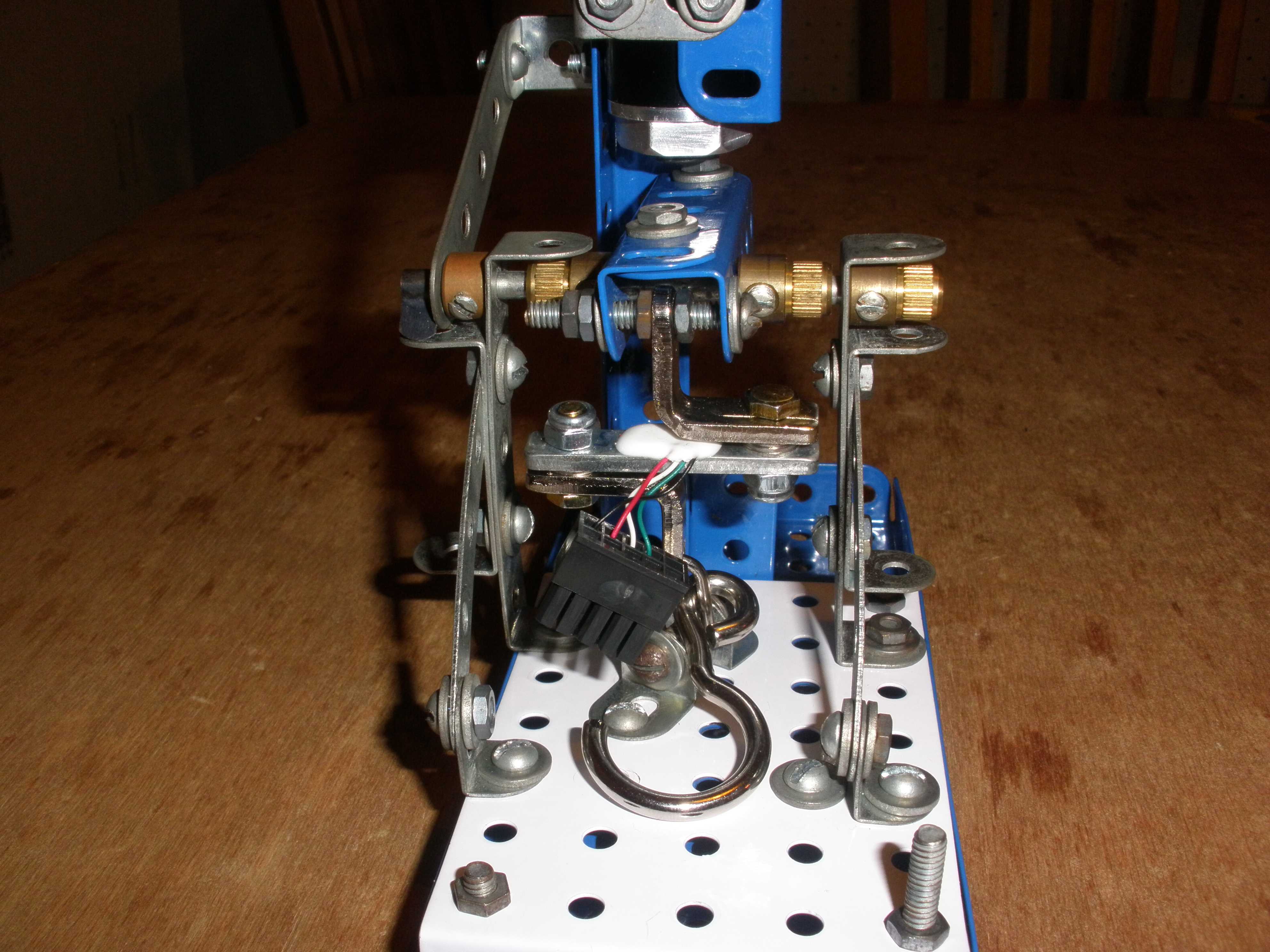
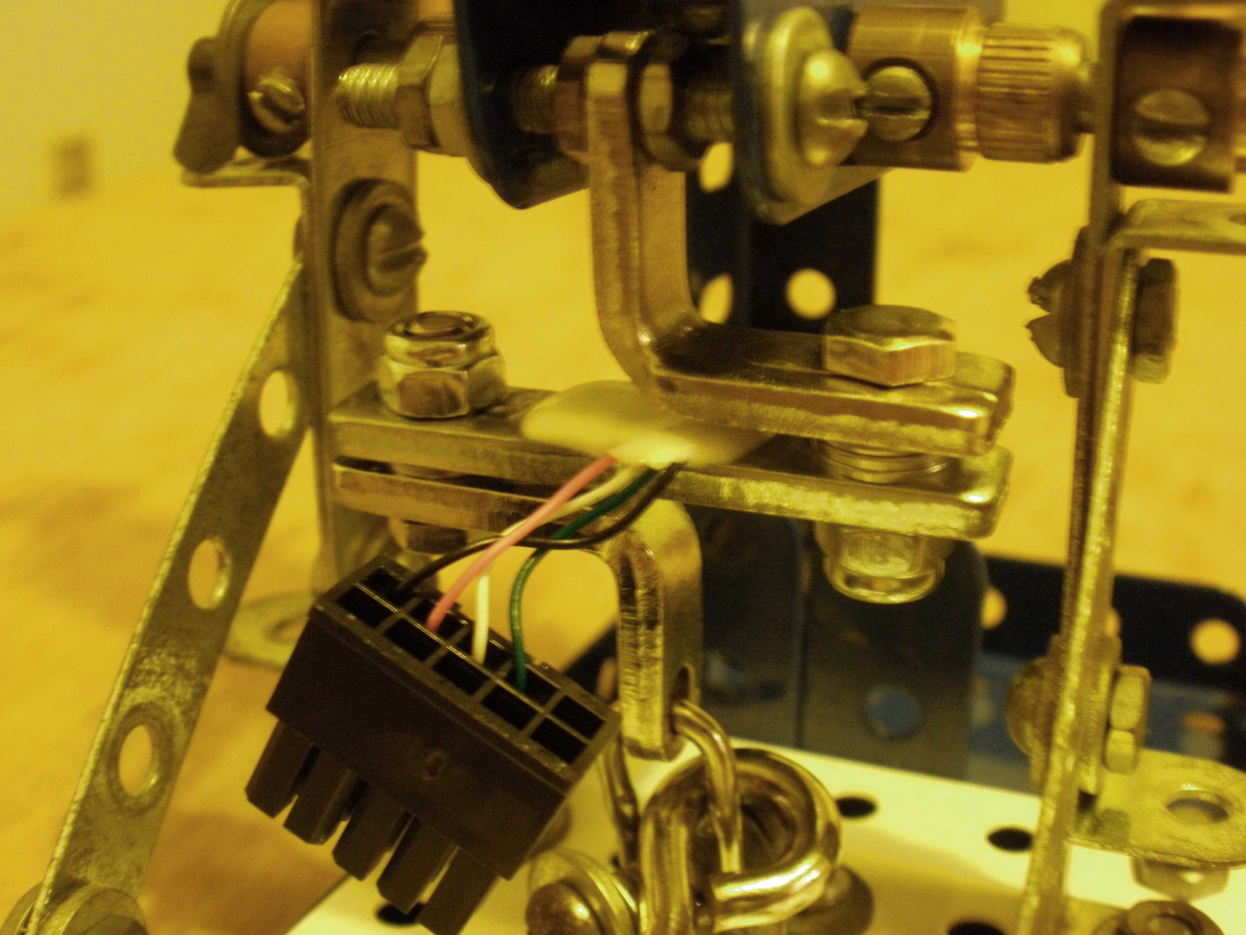
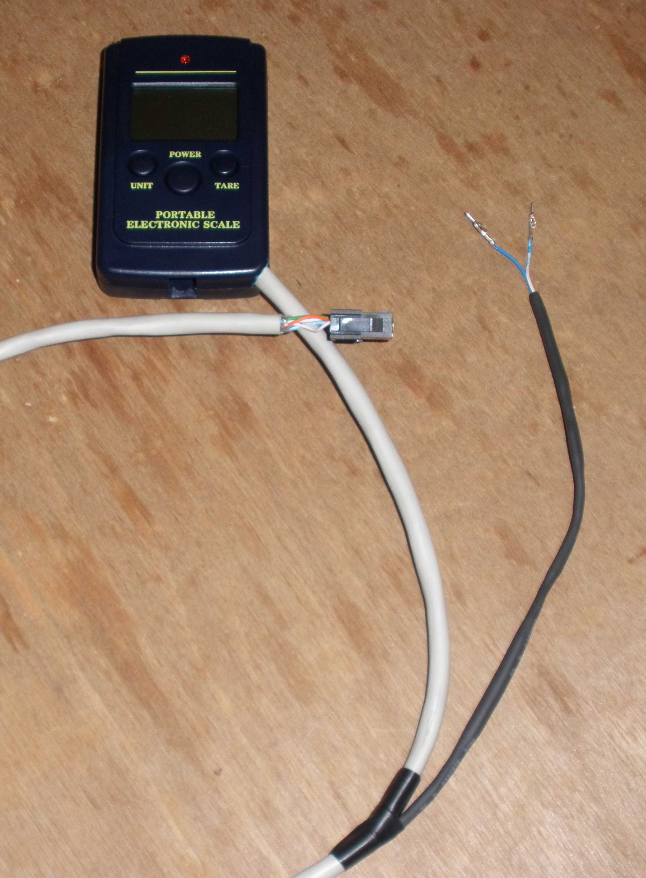
This is ripped out of a set of electronic scales. These scales are readily available from e-Bay for about £2.50 (including postage from China). The particular vendor I used seemed very good, and I would recommend them. There are UK e-Bay vendors supplying the same scales, but none as cheaply. To extract the load cell, you can see that I cut the wires joining it to the circuit board, and put on a plug. (I put a similar plug onto the other cut ends inside the box holding the circuit board). Since then I've decided that isn't such a good idea. There isn't really enough wire left on the load cell and it is very easy to break off the short pieces which are left when you're connecting and disconnecting the cable to the test stand. If I was doing it again I would definitely desolder the load cell at the circuit board (leaving it with much longer wires) and solder new wires to the circuit board so as to be able to mount the driver remotely. [Either that, or I would buy two and cut the wires long on one of the transducers and long on the other circuit board to give a fighting chance of adding the connectors without breaking or pulling out the wires].
Then I extended the wires from the circuit board, out of the box and terminated them in a socket that mates with the plug on the load cell. The other pair of wires split out from the main cable is a copy of the signal from the transducer that I will record using a data-logger (borrowed from work).
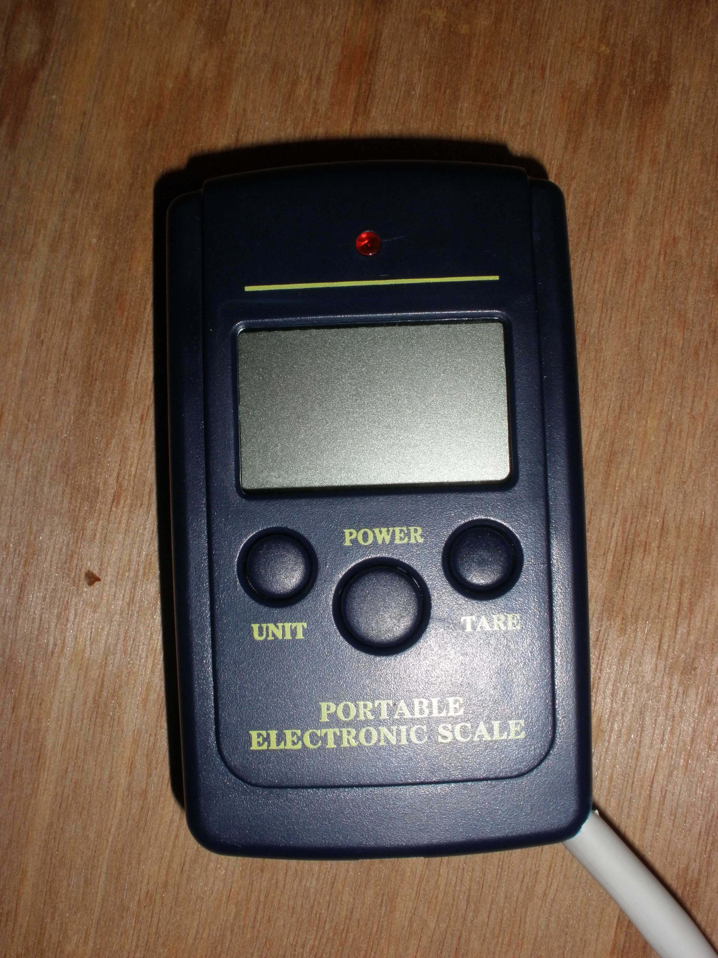
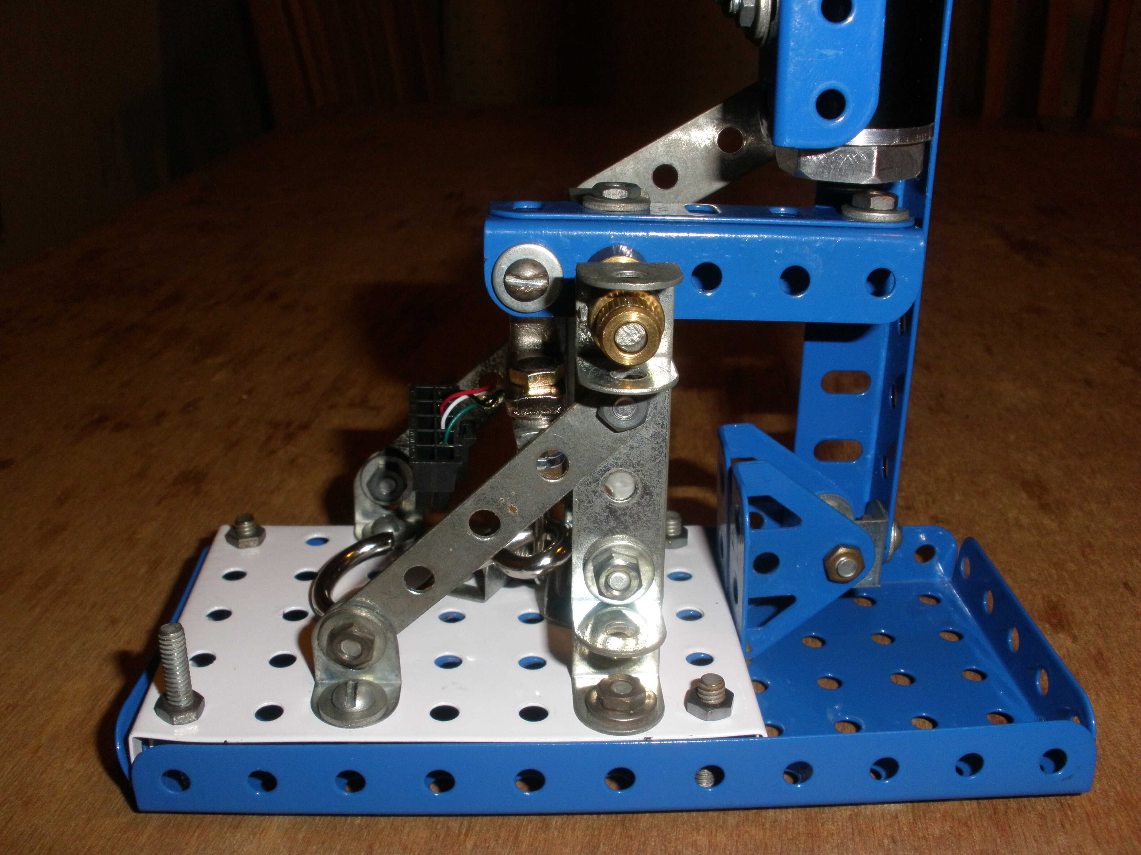
The scales weigh up to 40kgf (about 390N) and since I'm not expecting anything like that amount of thrust from the little motor, I have scaled up the measured signal so as to use more of the range of the transducer. The lever in the stand scales up the load by a factor of three.
Calibration
Not done it yet.
Results
I've tried the first firing in the stand! I found the logger hasn't a sensitive enough input range to permit direct logging from the strain gauge. So, until I make up an amplifier, I'm trying an alternative method of video recording the LCD display on the scales.
This short video shows the latest motor firing; the second showing is one quarter normal speed.
The motor worked very well, but the lighting for the video recording of the scales leaves a lot to be desired. [The camera I used for the scales, is the same camera as I use for in-flight video. It has no view finder. I managed to align it quite well in a dry run, but clearly didn't find the same position for the real thing. Roll on the amplifier and proper data logging].
I've recently tried again, still with no proper logging, but with better pictures of the scales' display when I tried using PVC pipe as a fuel.